APPENDIX C
TROUBLESHOOTING PROCEDURES
MALFUNCTION
TEST OR INSPECTION
CORRECTIVE ACTION
OXYACETYLENE WELDING
1. DISTORTION (fig. C-1)
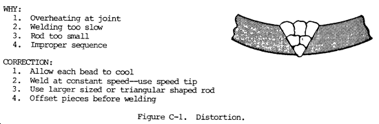
Step 1. Check to see whether shrinkage of deposited metal has pulled welded parts together.
a. Properly clamp or tack weld parts to resist shrinkage.
b. Separate or preform parts sufficiently to allow for shrinkage of welds.
c. Peen the deposited metal while still hot.
Step 2. Check for uniform heating of parts during welding.
a. Support parts of structure to be welded to prevent buckling in heated sections due to weight of parts themselves.
b. Preheating is desirable in some heavy structures.
c. Removal of rolling or forming strains before welding is sometimes helpful.
Step 3. Check for proper welding sequence.
a. Study the structure and develop a definite sequence of welding.
b. Distribute welding to prevent excessive local heating.
2. WELDING STRESSES
Step 1. Check the joint design for excessive rigidity.
a. Slight movement of parts during welding will reduce welding stresses.
b. Develop a welding procedure that permits all parts to be free to move as long as possible.
Step 2. Check for proper welding procedure.
a. Make weld in as few passes as practical.
b. Use special intermittent or alternating welding sequence and backstep or skip welding procedure.
c. Properly clamp parts adjacent to the joint. Use backup fixtures to cool parts rapidly.
Step 3. If no improper conditions exist, stresses could merely be those inherent in any weld, especially in heavy parts.
Peen each deposit of weld metal. Stress relieve finished product at 1100 to 1250°F (593 to 677°C) 1 hour per 1.0 in. (25.4 cm) of thickness.
3. WARPING OF THIN PLATES (fig. C-2)
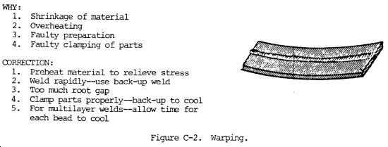
Step 1. Check for shrinkage of deposited weld metal.
Distribute heat input more evenly over full length of seam.
Step 2. Check for excessive local heating at the joint.
Weld rapidly with a minimum heat input to prevent excessive local heating of the plates adjacent to the weld.
Step 3. Check for proper preparation of the joint.
a. Do not have excessive space between the parts to be welded. Prepare thin plate edges with flanged joints, making offset approximately equal to the thickness of the plates. No filler rod is necessary for this type of joint.
b. Fabricate a U-shaped corrugation in the plates parallel to and approximately 1/2 in. (12.7 mm) away from the seam. This will serve as an expansion joint to take up movement during and after the welding operation.
Step 4. Check for proper welding procedure.
a. Use special welding sequence and backstep or skip procedure.
b. Preheat material to relieve stress.
Step 5. Check for proper clamping of parts.
Properly clamp parts adjacent to the joint. Use backup fixtures to cool parts rapidly.
4. POOR WELD APPEARANCE (fig. C-3)
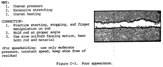
Step 1. Check the welding technique, flame adjustment, and welding rod manipulation.
a. Ensure the use of the proper welding technique for the welding rod used.
b. Do not use excessive heat.
c. Use a uniform weave and welding speed at all times.
Step 2. Check the welding rod used, as the poor appearance may be due to the inherent characteristics of the particular rod.
Use a welding rod designed for the type of weld being made.
Step 3. Check for proper joint preparation.
Prepare all joints properly.
5. CRACKED WELDS (fig. C-4)
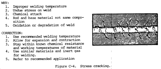
Step 1. Check the joint design for excessive rigidity.
Redesign the structure or modify the welding procedure in order to eliminate rigid joints.
Step 2. Check to see if the welds are too small for the size of the parts joined.
Do not use too small a weld between heavy plates. Increase the size of welds by adding more filler metal.
Step 3. Check for proper welding procedure.
a. Do not make welds in string beads. Deposit weld metal full size in short sections 8.0 to 10.0 in. (203.2 to 254.0 mm) long. (This is called block sequence.)
b. Welding sequence should be such as to leave ends free to move as long as possible.
c. Preheating parts to be welded sometimes helps to reduce high contraction stresses caused by localized high temperatures.
Step 4. Check for poor welds.
Make sure welds are sound and the fusion is good.
Step 5. Check for proper preparation of joints.
Prepare joints with a uniform and proper free space. In some cases a free space is essential. In other cases a shrink or press fit may be required.
6. UNDERCUT
Step 1. Check for excessive weaving of the bead, improper tip size, and insufficient welding rod added to molten puddle.
a. Modify welding procedure to balance weave of bead and rate of welding rod deposition, using proper tip size.
b. Do not use too small a welding rod.
Step 2. Check for proper manipulation of the welding.
a. Avoid excessive and nonuniform weaving.
b. A uniform weave with unvarying heat input will aid greatly in preventing undercut in butt welds.
Step 3. Check for proper welding technique -- improper welding rod deposition with nonuniform heating.
Do not hold welding rod too near the lower edge of the vertical plate when making a horizontal fillet weld, as undercut on the vertical plate will result.
7. INCOMPLETE PENETRATION (fig. C-5)
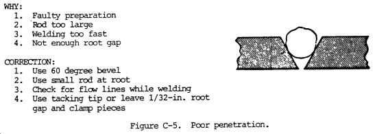
Step 1. Check for proper preparation of joint.
a. Be sure to allow the proper free space at the bottom of the weld.
b. Deposit a layer of weld metal on the back side of the joint, where accessible, to ensure complete fusion at the root of the joint.
Step 2. Check the size of the welding rod used.
a. Select proper sized welding rod to obtain a balance in the heat requirements for melting welding rod, breaking down side walls, and maintaining the puddle of molten metal at the desired size.
b. Use small diameter welding rods in a narrow welding groove.
Step 3. Check to see if welding tip is too small, resulting in insufficient heat input.
Use sufficient heat input to obtain proper penetration for the plate thickness being welded.
Step 4. Check for an excessive welding speed.
Welding speed should be slow enough to allow welding heat to penetrate to the bottom of the joint.
8. POROUS WELDS (fig. C-6)
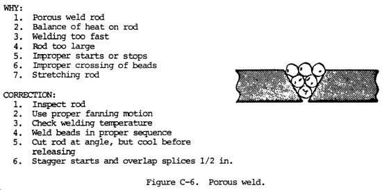
Step 1. Check the inherent properties of the particular type of welding rod.
Use welding rod of proper chemical analysis.
Step 2. Check the welding procedure and flame adjustment.
a. Avoid overheating molten puddle of weld metal.
b. Use the proper flame adjustment and flux, if necessary, to ensure sound welds.
Step 3. Check to see if puddling time is sufficient to allow entrapped gas, oxides, and slag inclusions to escape to the surface.
a. Use the multilayer welding technique to avoid carrying too large a molten puddle of weld metal.
b. Puddling keeps the weld metal longer and often ensures sounder welds.
Step 4. Check for poor base metal.
Modify the normal welding procedure to weld poor base metals of a given type.
9. BRITTLE WELDS
Step 1. Check for unsatisfactory welding rod, producing air-hardening weld metal.
Avoid welding rods producing air-hardening weld metal where ductility is desired. High tensile strength, low alloy steel rods are air-hardened and require proper base metal preheating, postheating, or both to avoid cracking due to brittleness.
Step 2. Check for excessive heat input from oversized welding tip, causing coarse-grained and burnt metal.
Do not use excessive heat input, as this may cause coarse grain structure and oxide inclusions in weld metal deposits.
Step 3. Check for high carbon or alloy base metal which has not been taken into consideration.
Welds may absorb alloy elements from the patent metal and become hard. Do not weld a steel unless the composition and characteristics are known.
Step 4. Check for proper flame adjustment and welding procedure.
a. Adjust the flare so that the molten metal does not boil, foam, or spark.
b. A single pass weld maybe more brittle than multilayer weld, because it has not been refined by successive layers of weld metal.
10. POOR FUSION (fig. C-7)
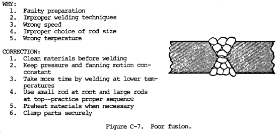
Step 1. Check the welding rod size.
When welding in narrow grooves, use a welding rod small enough to reach the bottom.
Step 2. Check the tip size and heat input.
Use sufficient heat to melt welding rod and to break down sidewalls of plate edges.
Step 3. Check the welding technique.
Be sure the weave is wide enough to melt the sides of the joint thoroughly.
Step 4. Check for proper preparation of the joint.
The deposited metal should completely fuse with the side walls of the plate metal to form a consolidated joint of base and weld metal.
11. CORROSION
Step 1. Check the type of welding rod used.
Select welding rods with the proper corrosion resistance properties which are not changed by the welding process.
Step 2. Check whether the weld deposit is proper for the corrosive fluid or atmosphere.
a. Use the proper flux on both parent metal and welding rod to produce welds with the desired corrosion resistance.
b. Do not expect more from the weld than from the parent metal. On stainless steels, use welding rods that are equal to or better than the base metal in corrosion resistance.
c. For best corrosion resistance, use a filler rod whose composition is the same as the base metal.
Step 3. Check the metallurgical effect of welding.
When welding 18-8 austenitic stainless steel, be sure the analysis of the steel and the welding procedure are correct, so that the welding process does not cause carbide precipitation. This condition can be corrected by annealing at 1900 to 2100°F (1038 to 1149°C).
Step 4. Check for proper cleaning of weld.
Certain materials such as aluminum require special procedures for thorough cleaning of all slag to prevent corrosion.
12. BRITTLE JOINTS
Step 1. Check base metal for air hardening characteristics.
In welding on medium carbon steel or certain alloy steels, the fusion zone may be hard as the result of rapid cooling. Preheating at 300 to 500°F (149 to 260°C) should be resorted to before welding.
Step 2. Check welding procedure.
Multilayer welds will tend to anneal hard zones. Stress relieving at 1000 to 1250°F (538 to 677°C) after welding generally reduce hard areas formed during welding.
Step 3. Check type of welding rod used.
The use of austenitic welding rods will often work on special steels, but the fusion zone will generally contain an alloy which is hard.
ARC WELDING
13. DISTORTION (fig. C-1)
Step 1. Check for shrinkage of deposited metal.
a. Properly tack weld or clamp parts to resist shrinkage.
b. Separate or preform parts so as to allow for shrinkage of welds.
c. Peen the deposited metal while still hot.
Step 2. Check for uniform heating of parts.
a. Preheating is desirable in some heavy structures.
b. Removal of rolling or forming strains by stress relieving before welding is sometimes helpful.
Step 3. Check the welding sequence.
a. Study structure and develop a definite sequence of welding.
b. Distribute welding to prevent excessive local heating.
14. WELDING STRESSES
Step 1. Check for excessive rigidity of joints.
a. Slight movement of parts during welding will reduce welding stresses.
b. Develop a welding procedure that permits all parts to be free to move as long as possible.
Step 2. Check the welding procedure.
a. Make weld in as few passes as practical.
b. Use special intermittent or alternating welding sequence and backstep or skip procedures.
c. Properly clamp parts adjacent to the joint. Use backup fixtures to cool parts rapidly.
Step 3. If no improper conditions exist, stresses could merely be those inherent in any weld, especially in heavy parts.
a. Peen each deposit of weld metal.
b. Stress relieve finished product at 1100 to 1250°F (593 to 677°C) 1 hour per 1.0 in. (25.4 cm) of thickness.
15. WARPING OF THIN PLATES (fig. C-2)
Step 1. Check for shrinkage of deposited weld metal.
Select electrode with high welding speed and moderate penetrating properties.
Step 2. Check for excessive local heating at the joint.
Weld rapidly to prevent excessive local heating of the plates adjacent to the weld.
Step 3. Check for proper preparation of joint.
a. Do not have excessive root opening in the joint between the parts to be welded.
b. Hammer joint edges thinner than the rest of the plates before welding. This elongates the edges and the weld shrinkage causes them to pull back to the original shape.
Step 4. Check the welding procedure.
a. Use special intermittent or alternating welding sequence and backstep or skip procedure.
b. Preheat material to achieve stress.
Step 5. Check the clamping of parts.
Properly clamp parts adjacent to the joint. Use backup fixtures to cool parts rapidly.
16. POOR WELD APPEARANCE (fig. C-3)
Step 1. Check welding technique for proper current and electrode manipulation.
a. Ensure the use of the proper welding technique for the electrode used.
b. Do not use excessive welding current.
c. Use a uniform weave or rate of travel at all times.
Step 2. Check characteristics of type of electrode used.
Use an electrode designed for the type of weld and base metal and the position in which the weld is to be made.
Step 3. Check welding position for which electrode is designed.
Do not make fillet welds with downhand (flat position) electrodes unless the parts are positioned properly.
Step 4. Check for proper joint preparation.
Prepare all joints properly.
17. CRACKED WELDS (fig. C-4)
Step 1. Check for excessive rigidity of joint.
Redesign the structure and modify the welding procedure in order to eliminate rigid joints.
Step 2. Check to see if the welds are too small for the size of the parts joined.
Do not use too small a weld between heavy plates. Increase the size of welds by adding more filler metal.
Step 3. Check the welding procedure.
a. Do not make welds in string beads. Deposit weld metal full size in short sections 8.0 to 10.0 in. (203.2 to 254.0 mm) long. (This is called block sequence.)
b. Welding sequence should be such as to leave ends free to move as long as possible.
c. Preheating parts to be welded sometimes helps to reduce high contraction stresses caused by localized high temperature.
d. Fill all craters at the end of the weld pass by moving the electrode back over the finished weld for a short distance equal to the length of the crater.
Step 4. Check for poor welds.
Make sure welds are sound and the fusion is good. Be sure arc length and polarity are correct.
Step 5. Check for proper preparation of joints.
Prepare joints with a uniform and proper root opening. In some cases, a root opening is essential. In other cases, a shrink or press fit may be required.
18. UNDERCUT
Step 1. Check the welding current setting.
Use a moderate welding sent and do not try to weld at too high a speed.
Step 2. Check for proper manipulation of the electrode.
a. Do not use too large an electrode. If the puddle of molten metal becomes too large, undercut may result.
b. Excessive width of weave will cause undercut and should not be used. A uniform weave, not over three times the electrode diameter, will aid greatly in preventing undercut in butt welds.
c. If an electrode is held to near the vertical plate in making a horizontal fillet weld, undercut on the vertical plate will result.
19. POOR PENETRATION (fig. C-5)
Step 1. Check to see if the electrode is designed for the welding position being used.
a. Electrodes should be used for welding in the position for which they were designed.
b. Be sure to allow the proper root openings at the bottom of a weld.
c. Use a backup bar if possible.
d. Chip or cut out the back of the joint and deposit a bead of weld metal at this point.
Step 2. Check size of electrode used.
a. Do not expect excessive penetration from an electrode.
b. Use small diameter electrodes in a narrow welding groove.
Step 3. Check the welding current setting.
Use sufficient welding current to obtain proper penetration. Do not weld too rapidly.
Step 4. Check the welding speed.
Control the welding speed to penetrate to the bottom of the welded joint.
20. POROUS WELDS (fig. C-6)
Step 1. Check the properties of the electrode used.
Some electrodes inherently produce sounder welds than others. Be sure that proper electrodes are used.
Step 2. Check welding procedure and current setting.
A weld made of a series of string beads may contain small pinholes. Weaving will often eliminate this trouble.
Step 3. Check puddling time to see whether it is sufficient to allow entrapped gas to escape.
Puddling keeps the weld metal molten longer and often insures sounder welds.
Step 4. Check for dirty base metal.
In some cases, the base metal may be at fault. Check this for segregations and impurities.
21. BRITTLE WELDS
Step 1. Check the type of electrode used.
Bare electrodes produce brittle welds. Shielded arc electrodes must be used if ductile welds are required.
Step 2. Check the welding current setting.
Do not use excessive welding current, as this may cause coarse-grained structure and oxidized deposits.
Step 3. Check for high carbon or alloy base metal which has not been taken into consideration.
a. A single pass weld may be more brittle than a multilayer weld because its microstructure has not been refined by successive layers of weld metal.
b. Welds may absorb alloy elements from the parent metal and become hard.
c. Do not weld a metal unless the composition and characteristics are known.
22. POOR FUSION (fig. C-7)
Step 1. Check diameter of electrode.
When welding in narrow groove joints use an electrode small enough to properly reach the bottom of the joint.
Step 2. Check the welding current setting.
a. Use sufficient welding current to deposit the metal and penetrate into the plates.
b. Heavier plates require higher current for a given electrode than light plates.
Step 3. Check the welding technique.
Be sure the weave is wide enough to melt the sidewalls of the joint thoroughly.
Step 4. Check the preparation of the joint.
The deposited metal should fuse with the base metal and not curl away from it or merely adhere to it.
23. CORROSION
Step 1. Check the type of electrode used.
a. Bare electrodes produce welds that are less resistant to corrosion than the parent metal.
b. Shield arc electrodes produce welds that are more resistant to corrosion than the parent metal.
c. For the best corrosion resistance, use a filler rod whose composition is similar to that of the base metal.
Step 2. Check to see if the weld metal deposited is proper for the corrosive fluid or atmosphere to be encountered.
Do not expect more from the weld than you do from the parent metal. On stainless steels, use electrodes that are equal to or better than the parent metal in corrosion resistance.
Step 3. Check on the metallurgical effect of the welding.
When welding 18-8 austenitic stainless steel, be sure the analysis of the steel and welding procedure is correct, so that the welding does not cause carbide precipitations. Carbide precipitation is the rising of carbon to the surface of the weld zone. This condition can be corrected by annealing at 1900 to 2100°F (1038 to 1149°C) after welding. By doing this corrosion in the form of iron oxide, or rust, can be eliminated.
Step 4. Check for proper cleaning of the weld.
Certain materials, such as aluminum, require careful cleaning of all slag after welding to prevent corrosion in service.
24. BRITTLE JOINTS
Step 1. Check for air hardening of the base metal.
In medium carbon steel or certain alloy steals, the heat affected zone may be hard as a result of rapid cooling. Preheating at 300 to 500°F (149 to 260°C) should be resorted to before welding.
Step 2. Check the welding procedure.
a. Multilayer welds will tend to anneal hard heat affected zones.
b. Stress relieving at 1100 to 1250°F (593 to 677°C) after welding will generally reduce hard areas formed during welding.
Step 3. Check the type of electrode used.
The use of austenitic electrodes will often be successful on special steels, but the heat-affected zone will generally contain an alloy which is hard.
25. MAGNETIC BLOW
Step 1. Check for deflection of the arc from its normal path, particularly at the ends of joints and in corners.
a. Make sure the ground is properly located on the work. Placing the ground in the direction of the arc deflection is often helpful.
b. Separating the ground into two or more parts is helpful.
c. Weld toward the direction in which the arc blows.
d. Hold a short arc.
e. Changing the angle of the electrode relative to the work may help to stabilize the arc.
f. Magnetic blow is held to a minimum in alternating current welding.
26. SPATTER
Step 1. Check the properties of the electrode used.
Select the proper type of electrode.
Step 2. Check to see if the welding current is excessive for the type and diameter of electrode used.
Use a short arc but do not use excessive welding current
Step 3. Check for spalls.
a. Paint parts adjacent to welds with whitewash or other protective coating. This prevents spalls from welding to parts, and they can be easily removed.
b. Coated electrodes produce larger spalls than bare electrodes.