CHAPTER 2 SAFETY PRECAUTIONS IN WELDING OPERATIONS
Section I. GENERAL SAFETY PRECAUTIONS
2-1. GENERAL
a. To prevent injury to personnel, extreme caution should be exercised when using any types of welding equipment. Injury can result from fire, explosions, electric shock, or harmful agents. Both the general and specific safety precautions listed below must be strictly observed by workers who weld or cut metals.
b. Do not permit unauthorized persons to use welding or cutting equipment.
c. Do not weld in a building with wooden floors, unless the floors are protected from hot metal by means of fire resistant fabric, sand, or other fireproof material. Be sure that hot sparks or hot metal will not fall on the operator or on any welding equipment components.
d. Remove all flammable material, such as cotton, oil, gasoline, etc., from the vicinity of welding.
e. Before welding or cutting, warm those in close proximity who are not protected to wear proper clothing or goggles.
f. Remove any assembled parts from the component being welded that may become warped or otherwise damaged by the welding process.
g. Do not leave hot rejected electrode stubs, steel scrap, or tools on the floor or around the welding equipment. Accidents and/or fires may occur.
h. Keep a suitable fire extinguisher nearby at all times. Ensure the fire extinguisher is in operable condition.
i. Mark all hot metal after welding operations are completed. Soapstone is commonly used for this purpose.
2-2. PERSONAL PROTECTIVE EQUIPMENT
a. General. The electric arc is a very powerful source of light, including visible, ultraviolet, and infrared. Protective clothing and equipment must be worn during all welding operations. During all oxyacetylene welding and cutting proccesses, operators must use safety goggles to protect the eyes from heat, glare, and flying fragments of hot metals. During all electric welding processes, operators must use safety goggles and a hand shield or helmet equipped with a suitable filter glass to protect against the intense ultraviolet and infrared rays. When others are in the vicinity of the electric welding processes, the area must be screened so the arc cannot be seen either directly or by reflection from glass or metal.
b. Helmets and Shields.
(1) Welding arcs are intensely brilliant lights. They contain a proportion of ultraviolet light which may cause eye damage. For this reason, the arc should never be viewed with the naked eye within a distance of 50.0 ft (15.2 m). The brilliance and exact spectrum, and therefore the danger of the light, depends on the welding process, the metals in the arc, the arc atmosphere, the length of the arc, and the welding current. Operators, fitters, and those working nearby need protection against arc radiation. The intensity of the light from the arc increases with increasing current and arc voltage. Arc radiation, like all light radiation, decreases with the square of the distance. Those processes that produce smoke surrounding the arc have a less bright arc since the smoke acts as a filter. The spectrum of the welding arc is similar to that of the sun. Exposure of the skin and eyes to the arc is the same as exposure to the sun.
(2) Being closest, the welder needs a helmet to protect his eyes and face from harmful light and particles of hot metal. The welding helmet (/fig. 2-1) is generally constructed of a pressed fiber insulating material. It has an adjustable headband that makes it usable by persons with different head sizes. To minimize reflection and glare produced by the intense light, the helmet is dull black in color. It fits over the head and can be swung upward when not welding. The chief advantage of the helmet is that it leaves both hands free, making it possible to hold the work and weld at the same time.
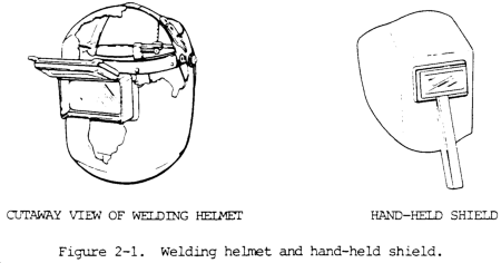
(3) The hand-held shield (
/fig. 2-1) provides the same protection as the helmet, but is held in position by the handle. This type of shield is frequently used by an observer or a person who welds for a short period of time.
(4) The protective welding helmet has lens holders used to insert the cover glass and the filter glass or plate. Standard size for the filter plate is 2 x 4-1/4 in. (50 x 108 mm). In some helmets lens holders open or flip upwards. Lenses are designed to prevent flash burns and eye damage by absorption of the infrared and ultraviolet rays produced by the arc. The filter glasses or plates come in various optical densities to filter out various light intensities, depending on the welding process, type of base metal, and the welding current. The color of the lens, usually green, blue, or brown, is an added protection against the intensity of white light or glare. Colored lenses make it possible to clearly see the metal and weld. Table 2-1 lists the proper filter shades to be used. A magnifier lens placed behind the filter glass is sometimes used to provide clear vision.

A cover plate should be placed outside the filter glass to protect it from weld spatter. The filter glass must be tempered so that is will not break if hit by flying weld spatter. Filter glasses must be marked showing the manufacturer, the shade number, and the letter “H” indicating it has been treated for impact resistance.
NOTE
Colored glass must be manufactured in accordance with specifications detailed in the “National Safety Code for the Protection of Hands and Eyes of Industrial Workers”, issued by the National Bureau of Standards, Washington DC, and OSHA Standards, Subpart Q, “Welding, Cutting, and Brazing”, paragraph 1910.252, and American National Standards Institute Standard (ANSI) Z87.1-1968, “American National Standard Practice for Occupational and Educational Eye and Face Protection”.
(5) Gas metal-arc (MIG) welding requires darker filter lenses than shielded metal-arc (stick) welding. The intensity of the ultraviolet radiation emitted during gas metal-arc welding ranges from 5 to 30 times brighter than welding with covered electrodes.
(6) Do not weld with cracked or defective shields because penetrating rays from the arc may cause serious burns. Be sure that the colored glass plates are the proper shade for arc welding. Protect the colored glass plate from molten metal spatter by using a cover glass. Replace the cover glass when damaged or spotted by molten metal spatter.
(7) Face shields (/fig. 2-2) must also be worn where required to protect eyes. welders must wear safety glasses and chippers and grinders often use face shields in addition to safety glasses.
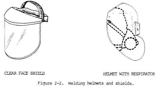
(8) In some welding operations, the use of mask-type respirators is required. Helmets with the “bubble” front design can be adapted for use with respirators.
c. Safety Goggles. During all electric welding processes, operators must wear safety goggles (/fig. 2-3) to protect their eyes from weld spatter which occasionally gets inside the helmet. These clear goggles also protect the eyes from slag particles when chipping and hot sparks when grinding. Contact lenses should not be worn when welding or working around welders. Tinted safety glasses with side shields are recommended, especially when welders are chipping or grinding. Those working around welders should also wear tinted safety glasses with side shields.

d.
Protective Clothing.
(1) Personnel exposed to the hazards created by welding, cutting, or brazing operations shall be protected by personal protective equipment in accordance with OSHA standards, Subpart I, Personal Protective Equipment, paragraph 1910.132. The appropriate protective clothing (/fig. 2-4) required for any welding operation will vary with the size, nature, and location of the work to be performed. Welders should wear work or shop clothes without openings or gaps to prevent arc rays from contacting the skin. Those working close to arc welding should also wear protective clothing. Clothing should always be kept dry, including gloves.
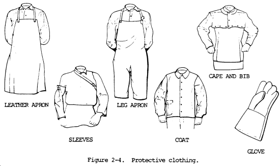
(2) Woolen clothing should be worn instead of cotton since wool is not easily burned or damaged by weld spatter and helps to protect the welder from changes in temperature. Cotton clothing, if used, should be chemically treated to reduce its combustibility. All other clothing, such as jumpers or overalls, should be reasonably free from oil or grease.
(3) Flameproof aprons or jackets made of leather, fire resistant material, or other suitable material should be worn for protection against spatter of molten metal, radiated heat, and sparks. Capes or shoulder covers made of leather or other suitable materials should be worn during overhead welding or cutting operations. Leather skull caps may be worn under helmets to prevent head burns.
(4) Sparks may lodge in rolled-up sleeves, pockets of clothing, or cuffs of overalls and trousers. Therefore, sleeves and collars should be kept buttoned and pockets should be eliminated from the front of overalls and aprons. Trousers and overalls should not be turned up on the outside. For heavy work, fire-resisant leggings, high boots, or other equivalent means should be used. In production work, a sheet metal screen in front of the worker’s legs can provide further protection against sparks and molten metal in cutting operations.
(5) Flameproof gauntlet gloves, preferably of leather, should be worn to protect the hands and arms from rays of the arc, molten metal spatter, sparks, and hot metal. Leather gloves should be of sufficient thickness so that they will not shrivel from the heat, burn through, or wear out quickly. Leather gloves should not be used to pick up hot items, since this causes the leather to become stiff and crack. Do not allow oil or grease to cane in contact with the gloves as this will reduce their flame resistance and cause them to be readily ignited or charred.
e. Protective Equipment.
(1) Where there is exposure to sharp or heavy falling objects or a hazard of bumping in confined spaces, hard hats or head protectors must be used.
(2) For welding and cutting overhead or in confined spaces, steel-toed boots and ear protection must also be used.
(3) When welding in any area, the operation should be adequately screened to protect nearby workers or passers-by froman the glare of welding. The screens should be arranged so that no serious restriction of ventilation exists. The screens should be mounted so that they are about 2.0 ft above the floor unless the work is performed at such a low level that the screen must be extended closer to the floor to protect adjacent workers. The height of the screen is normally 6.0 ft (1.8 m) but may be higher depending upon the situation. Screen and surrounding areas must be painted with special paints which absorb ultraviolet radiation yet do not create high contrast between the bright and dark areas. Light pastel colors of a zinc or titanium dioxide base paint are recommended. Black paint should not be used.
2-3. FIRE HAZARDS
a. Fire prevention and protection is the responsibility of welders, cutters, and supervisors. Approximately six percent of the fires in industrial plants are caused by cutting and welding which has been done primarily with portable equipment or in areas not specifically designated for such work. The elaboration of basic precautions to be taken for fire prevention during welding or cutting is found in the Standard for Fire Prevention in Use of Cutting and Welding Processes, National Fire Protection Association Standard 51B, 1962. Some of the basic precautions for fire prevention in welding or cutting work are given below.
b. During the welding and cutting operations, sparks and molten spatter are formal which sometimes fly considerable distances. Sparks have also fallen through cracks, pipe holes, or other small openings in floors and partitions, starting fires in other areas which temporarily may go unnoticed. For these reasons, welding or cutting should not be done near flammable materials unless every precaution is taken to prevent ignition.
c. Hot pieces of base metal may come in contact with combustible materials and start fires. Fires and explosions have also been caused when heat is transmitted through walls of containers to flammable atmospheres or to combustibles within containers. Anything that is combustible or flammable is susceptible to ignition by cutting and welding.
d. When welding or cutting parts of vehicles, the oil pan, gasoline tank, and other parts of the vehicle are considered fire hazards and must be removed or effectively shielded from sparks, slag, and molten metal.
e. Whenever possible, flammable materials attached to or near equipment requiring welding, brazing, or cutting will be removed. If removal is not practical, a suitable shield of heat resistant material should be used to protect the flammable material. Fire extinguishing equipment, for any type of fire that may be encountered, must be present.
2-4. HEALTH PROTECTION AND VENTILATION
a. General.
(1) All welding and thermal cutting operations carried on in confined spaces must be adequately ventilated to prevent the accumulation of toxic materials, combustible gases, or possible oxygen deficiency. Monitoring instruments should be used to detect harmful atmospheres. Where it is impossible to provide adequate ventilation, air-supplied respirators or hose masks approved for this purpose must be used. In these situations, lookouts must be used on the outside of the confined space to ensure the safety of those working within. Requirements in this section have been established for arc and gas welding and cutting. These requirements will govern the amount of contamination to which welders may be exposed:
(a) Dimensions of the area in which the welding process takes place (with special regard to height of ceiling).
(b) Number of welders in the room.
(c) Possible development of hazardous fumes, gases, or dust according to the metals involved.
(d) Location of welder’s breathing zone with respect to rising plume of fumes.
(2) In specific cases, there are other factors involved in which respirator protective devices (ventilation) should be provided to meet the equivalent requirements of this section. They include:
(a) Atomspheric conditions.
(b) Generated heat.
(c) Presence of volatile solvents.
(3) In all cases, the required health protection, ventilation standards, and standard operating procedures for new as well as old welding operations should be coordinated and cleaned through the safety inspector and the industrial hygienist having responsibility for the safety and health aspects of the work area.
b. Screened Areas. When welding must be performed in a space entirely screened on all sides, the screens shall be arranged so that no serious restriction of ventilation exists. It is desirable to have the screens mounted so that they are about 2.0 ft (0.6 m) above the floor, unless the work is performed at such a low level that the screen must be extended closer to the floor to protect workers from the glare of welding. See paragraph 2-2 e (3).
c. Concentration of Toxic Substances. Local exhaust or general ventilating systems shall be provided and arranged to keep the amount of toxic frees, gas, or dusts below the acceptable concentrations as set by the American National Standard Institute Standard 7.37; the latest Threshold Limit Values (TLV) of the American Conference of Governmental Industrial Hygienists; or the exposure limits as established by Public Law 91-596, Occupational Safety and Health Act of 1970. Compliance shall be determined by sampling of the atmsphere. Samples collected shall reflect the exposure of the persons involved. When a helmet is worn, the samples shall be collected under the helmet.
NOTE
Where welding operations are incidental to general operations, it is considered good practice to apply local exhaust ventilation to prevent contamination of the general work area.
d. Respiratory Protective Equipment. Individual respiratory protective equipment will be well retained. Only respiratory protective equipment approved by the US Bureau of Mines, National Institute of Occupational Safety and Health, or other government-approved testing agency shall be utilized. Guidance for selection, care, and maintenance of respiratory protective equipment is given in Practices for Respiratory Protection, American National Standard Institute Standard 788.2 and TB MED 223. Respiratory protective equipment will not be transferred from one individual to another without being disinfected.
e. Precautionary Labels. A number of potentially hazardous materials are used in flux coatings, coverings, and filler metals. These materials, when used in welding and cutting operations, will become hazardous to the welder as they are released into the atmosphere. These include, but are not limited to, the following materials: fluorine compounds, zinc, lead, beryllium, cadmium, and mercury. See paragraph 2-4 i through 2-4 n. The suppliers of welding materials shall determine the hazard, if any, associated with the use of their materials in welding, cutting, etc.
(1) All filler metals and fusible granular materials shall carry the following notice, as a minimum, on tags, boxes, or other containers:
CAUTION
Welding may produce fumes and gases hazardous to health. Avoid breathing these fumes and gases. Use adequate ventilation. See American National Standards Institute Standard Z49.1-1973, Safety in Welding and Cutting published by the American Welding Society.
(2) Brazing (welding) filler metals containing cadmium in significant amounts shall carry the following notice on tags, boxes, or other containers:
WARNING CONTAINS CADMIUM – POISONOUS FUMES MAY BE FORMED ON HEATING
Do not breathe fumes. Use only with adequate ventilation, such as fume collectors, exhaust ventilators, or air-supplied respirators. See American National Standards Institute Standard Z49.1-1973. If chest pain, cough, or fever develops after use, call physician immediately.
(3) Brazing and gas welding fluxes containing fluorine compounds shall have a cautionary wording. One such wording recommended by the American Welding Society for brazing and gas welding fluxes reads as follows:
CAUTION CONTAINS FLUORIDES
This flux, when heated, gives off fumes that may irritate eyes, nose, and throat. Avoid fumes–use only in well-ventilated spaces. Avoid contact of flux with eyes or skin. Do not take internally.
f. Ventilation for General Welding and Cutting.
(1) General. Mechanical ventilation shall be provided when welding or cutting is done on metals not covered in subparagraphs i through p of this section, and under the following conditions:
(a) In a space of less than 10,000 cu ft (284 cu m) per welder.
(b) In a roan having a ceiling height of less than 16 ft (5 m).
(c) In confined spaces or where the welding space contains partitions, balconies, or other structural barriers to the extent that they significantly obstruct cross ventilation.
(2) Minimum rate. Ventilation shall be at the minimum rate of 200 cu ft per minute (57 cu m) per welder, except where local exhaust heeds, as in paragraph 2-4 g below, or airline respirators approved by the US Bureau of Mines, National Institute of Occupational Safety and Health, or other government-approved testing agency, are used. When welding with rods larger than 3/16 in. (0.48 cm) in diameter, the ventilation shall be higher as shown in the following:
| Rod diameter (inches) |
Required ventilation (cfm) |
| 1/4 (0.64 cm) |
3500 |
| 3/8 (0.95 cm) |
4500 |
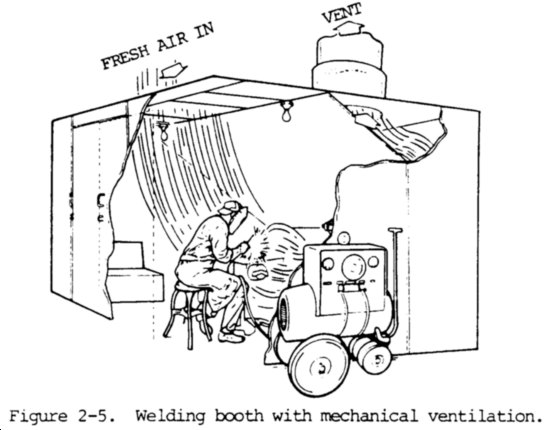
Natural ventilation is considered sufficient for welding or cutting operations where the conditions listed above are not present. Figure 2-5 is an illustration of a welding booth equipped with mechanical ventilation sufficient for one welder.
g.
Local Exhaust Ventilation. Mechanical local exhaust ventilation may be obtained by either of the following means:
(1) Hoods. Freely movable hoods or ducts are intended to be placed by the welder as near as practicable to the work being welded. These will provide a rate of airflow sufficient to maintain a velocity the direction of the hood of 100 in linear feet per minute in the zone of welding. The ventilation rates required to accomplish this control velocity using a 3-in. wide flanged suction opening are listed in table 2-2.

(2)
Fixed enclosure. A fixed enclosure with a top and two or more sides which surrounds the welding or cutting operations will have a rate of airflow sufficient to maintain a velocity away from the welder of not less than 100 linear ft per minute. Downdraft ventilation tables require 150 cu ft per minute per square foot of surface area. This rate of exhausted air shall be uniform across the face of the grille. A low volume, high-density fume exhaust device attached to the welding gun collects the fumes as close as possible to the point of origin or at the arc. This method of fume exhaust has become quite popular for the semiautomatic processes, particularly the flux-cored arc welding process. Smoke exhaust systems incorporated in semiautomatic guns provide the most economical exhaust system since they exhaust much less air they eliminate the need for massive air makeup units to provide heated or cooled air to replace the air exhausted. Local ventilation should have a rate of air flow sufficient to maintain a velocity away from the welder of not less than 100 ft (30 m) per minute. Air velocity is measurable using a velometer or air flow inter. These two systems can be extremely difficult to use when welding other than small weldments. The down draft welding work tables are popular in Europe but are used to a limited degree North America. In all cases when local ventilation is used, the exhaust air should be filtered.
h. Ventilation in Confined Spaces.
(1) Air replacement. Ventilation is a perquisite to work in confined spaces. All welding and cutting operations in confined spaces shall be adequately ventilated to prevent the accumulation of toxic materials -or possible oxygen deficiency. This applies not only to the welder but also to helpers and other personnel in the immediate vicinity.
(2) Airline respirators. In circumstances where it is impossible to provide adequate ventilation in a confined area, airline respirators or hose masks, approved by the US Bureau of Mines, National Institute of Occupational Safety and Health, or other government-approved testing agency, will be used for this purpose. The air should meet the standards established by Public Law 91-596, Occupational Safety and Health Act of 1970.
(3) Self-contained units. In areas immediately hazardous to life, hose masks with blowers or self-contained breathing equipment shall be used. The breathing equipment shall be approved by the US Bureau of Mines or National Institute of Occupational Safety and Health, or other government-approved testing agency.
(4) Outside helper. Where welding operations are carried on in confined spaces and where welders and helpers are provided with hose masks, hose masks with blowers, or self-contained breathing equipment, a worker shall be stationed on the outside of such confined spaces to ensure the safety of those working within.
(5) Oxygen for ventilation. Oxygen must never be used for ventilation.
i. Fluorine Compounds.
(1) General. In confined spaces, welding or cutting involving fluxes, coverings, or other materials which fluorine compounds shall be done in accordance with paragraph 2-4 h, ventilation in confined spaces. A fluorine compound is one that contains fluorine as an element in chemical combination, not as a free gas.
(2) Maximum allowable concentration. The need for local exhaust ventilation or airline respirators for welding or cutting in other than confined spaces will depend upon the individual circumstances. However, experience has shown that such protection is desirable for fixed-location production welding and for all production welding on stainless steels. When air samples taken at the welding location indicate that the fluorides liberated are below the maximum allowable concentration, such protection is not necessary.
j. Zinc.
(1) Confined spaces. In confined spaces, welding or cutting involving zinc-bearing filler metals or metals coated with zinc-bearing materials shall be done in accordance with paragraph 2-4 h, ventilation in confined spaces.
(2) Indoors. Indoors, welding or cutting involving zinc-bearing metals or filler metals coated with zinc-bearing materials shall be done in accordance with paragraph 2-4 g.
k. Lead.
(1) Confined spaces. In confined spaces, welding involving lead-base metals (erroneously called lead-burning) shall be done in accordance with paragraph 2-4 h.
(2) Indoors. Indoors, welding involving lead-base metals shall be done in accordance with paragraph 2-4 g, local exhaust ventilation.
(3) Local ventilation. In confined spaces or indoors, welding or cutting involving metals containing lead or metals coated with lead-bearing materials, including paint, shall be done using local exhaust ventilation or airline respirators. Outdoors, such operations shall be done using respirator protective equipment approved by the US Bureau of Mines, National Institute of Occupational Safety and Health, or other government-approved testing agency. In all cases, workers in the immediate vicinity of the cutting or welding operation shall be protected as necessary by local exhaust ventilation or airline respirators.
l. Beryllium. Welding or cutting indoors, outdoors, or in confined spaces involving beryllium-bearing material or filler metals will be done using local exhaust ventilation and airline respirators. This must be performed without excep-tion unless atmospheric tests under the most adverse conditions have established that the workers’ exposure is within the acceptable concentrations of the latest Threshold Limit Values (TLV) of the American Conference of Governmental Industrial Hygienists, or the exposure limits established by Public Law 91-596, Occupational Safety and Health Act of 1970. In all cases, workers in the immediate vicinity of the welding or cutting operations shall be protected as necessary by local exhaust ventilation or airline respirators.
m. Cadmium.
(1) General. Welding or cutting indoors or in confined spaces involving cadmium-bearing or cadmium-coated base metals will be done using local exhaust ventilation or airline respirators. Outdoors, such operations shall be done using respiratory protective equipment such as fume respirators, approved by the US Bureau of Mines, National Institute of Occupational Safety and Health, or other government-approved testing agency, for such purposes.
(2) Confined space. Welding (brazing) involving cadmium-bearing filler metals shall be done using ventilation as prescribed in paragraphs 2-4 g, local exhaust ventilation, and 2-4 h, ventilation in confined spaces, if the work is to be done in a confined space.
NOTE
Cadmium-free rods are available and can be used in most instances with satisfactory results.
n. Mercury. Welding or cutting indoors or in a confined space involving metals coated with mercury-bearing materials, including paint, shall be done using local exhaust ventilation or airline respirators. Outdoors, such operations will be done using respiratory protective equipment approved by the National Institute of Occupational Safety and Health, US Bureau of Mines, or other government-approved testing agency.
o. Cleaning Compounds.
(1) Manufacturer’s instructions. In the use of cleaning materials, because of their toxicity of flammability, appropriate precautions listed in the manufacturer’s instructions will be followed.
(2) Degreasing. Degreasing or other cleaning operations involving chlorinated hydrocarbons will be located so that no vapors from these operations will reach or be drawn into the area surrounding any welding operation. In addition, trichloroethylene and perchloroethylene should be kept out of atmospheres penetrated by the ultraviolet radiation of gas-shielded welding operations.
p. Cutting of Stainless Steels. Oxygen cutting, using either a chemical flux or iron powder, or gas-shielded arc cutting of stainless steel will be done using mechanical ventilation adequate to remove the fumes generated.
q. First-Aid Equipment. First-aid equipment will be available at all times. On every shift of welding operations, there will be personnel present who are trained to render first-aid. All injuries will be reported as soon as possible for medical attention. First-aid will be rendered until medical attention can be provided.
2-5. WELDING IN CONFINED SPACES
a. A confined space is intended to mean a relatively small or restricted space such as a tank, boiler, pressure vessel, or small compartment of a ship or tank.
b. When welding or cutting is being performed in any confined space, the gas cylinders and welding machines shall be left on the outside. Before operations are started, heavy portable equipment mounted on wheels shall be securely blocked to prevent accidental movement.
c. Where a welder must enter a confined space through a manhole or other all opening, means will be provided for quickly removing him in case of emergency. When safety belts and life lines are used for this purpose, they will be attached to the welder’s body so that he cannot be jammed in a small exit opening. An attendant with a preplanned rescue procedure will be stationed outside to observe the welder at all times and be capable of putting rescue operations into effect.
d. When arc welding is suspended for any substantial period of time, such as during lunch or overnight, all electrodes will be removed from the holders with the holders carefully located so that accidental contact cannot occur. The welding machines will be disconnected from the power source.
e. In order to eliminate the possibility of gas escaping through leaks or improperly closed valves when gas welding or cutting, the gas and oxygen supply valves will be closed, the regulators released, the gas and oxygen lines bled, and the valves on the torch shut off when the equipment will not be used for a substantial period of time. Where practical, the torch and hose will also be removed from the confined space.
f. After welding operations are completed, the welder will mark the hot metal or provide some other means of warning other workers.
Section II. SAFETY PRECAUTIONS IN OXYFUEL WELDING
2-6. GENERAL
a. In addition to the information listed in section I of this chapter, the following safety precautions must be observed.
b. Do not experiment with torches or regulators in any way. Do not use oxygen regulators with acetylene cylinders. Do not use any lubricants on regulators or tanks.
c. Always use the proper tip or nozzle, and always operate it at the proper pressure for the particular work involved. This information should be taken from work sheets or tables supplied with the equipment.
d. When not in use, make sure the torch is not burning. Also, release the regulators, bleed the hoses, and tightly close the valves. Do not hang the torch with its hose on the regulator or cylinder valves.
e. Do not light a torch with a match or hot metal, or in a confined space. The explosive mixture of acetylene and oxygen might cause personal injury or property damage when ignited. Use friction lighters or stationary pilot flames.
f. When working in confined spaces, provide adequate ventilation for the dissipation of explosive gases that may be generated. For ventilation standards, refer to paragraph 2-4, Health Protection and Ventilation.
g. Keep a clear space between the cylinder and the work so the cylinder valves can be reached easily and quickly.
h. Use cylinders in the order received. Store full and empty cylinders separately and mark the empty ones with “MT”.
i. Compressed gas cylinders owned by commercial companies will not be painted regulation Army olive drab.
j. Never use cylinders for rollers, supports, or any purpose other than thatfor which they are intended.
k. Always wear protective clothing suitable for welding or flame cutting.
l. Keep work area clean and free from hazardous materials. When flame cutting, sparks can travel 30 to 40 ft (9 to 12 m). Do not allow flare cut sparks to hit hoses, regulators, or cylinders.
m. Use oxygen and acetylene or other fuel gases with the appropriate torches and only for the purpose intended.
n. Treat regulators with respect. Do not turn valve handle using force.
o. Always use the following sequence and technique for lighting a torch:
(1) Open acetylene cylinder valve.
(2) Open acetylene torch valve 1/4 turn.
(3) Screw in acetylene regulator adjusting valve handle to working pressure.
(4) Turn off the acetylene torch valve (this will purge the acetylene line).
(5) Slowly open oxygen cylinder valve all the way.
(6) Open oxygen torch valve 1/4 turn.
(7) Screw in oxygen regulator screw to working pressure.
(8) Turn off oxygen torch valve (this will purge the oxygen line).
(9) Open acetylene torch valve 1/4 turn and light with lighter.
NOTE
Use only friction type lighter or specially provided lighting device.
(10) Open oxygen torch valve 1/4 turn.
(11) Adjust to neutral flame.
p. Always use the following sequence and technique for shutting off a torch:
(1) Close acetylene torch valve first, then the oxygen valve.
(2) Close acetylene cylinder valve, then oxygen cylinder valve.
(3) Open torch acetylene and oxygen valves to release pressure in the regulator and hose.
(4) Back off regulator adjusting valve handle until no spring tension is left.
(5) Close torch valves.
q. Use mechanical exhaust at the point of welding when welding or cutting lead, cadmium, chronium, manganese, brass, bronze, zinc, or galvanized steel.
r. Do not weld or flame cut on containers that have held combustibles without taking special precautions.
s. Do not weld or flame cut into sealed container or compartment without providing vents and taking special precautions.
t. Do not weld or cut in a confined space without taking special precautions.
2-7. ACETYLENE CYLINDERS
CAUTION
If acetylene cylinders have been stored or transported horizontally (on their sides), stand cylinders vertically (upright) for 45 minutes prior to (before) use.
a. Always refer to acetylene by its full name and not by the word “gas” alone. Acetylene is very different from city or furnace gas. Acetylene is a compound of carbon and hydrogen, produced by the reaction of water and calcium carbide.
b. Acetylene cylinders must be handled with care to avoid damage to the valves or the safety fuse plug. The cylinders must be stored upright in a well ventilated, well protected, dry location at least 20 ft from highly combustible materials such as oil, paint, or excelsior. Valve protection caps must always be in place, handtight, except when cylinders are in use. Do not store the cylinders near radiators, furnaces, or in any are with above normal temperatures. In tropical climates, care must be taken not to store acetylene in areas where the temperature is in excess of 137°F (58°C). Heat will increase the pressure, which may cause the safety fuse plug in the cylinder to blow out. Storage areas should be located away from elevators, gangways, or other places where there is danger of cylinders being knocked over or damaged by falling objects.
c. A suitable truck, chain, or strap must be used to prevent cylinders from falling or being knocked over while in use. Cylinders should be kept at a safe distance from the welding operation so there will be little possivility of sparks, hot slag, or flames reaching them. They should be kept away from radiators, piping systems, layout tables, etc., which may be used for grounding electrical circuits. Nonsparking tools should be used when changing fittings on cylinders of flammable gases.
d. Never use acetylene without reducing the pressure with a suitable pressure reducing regulator. Never use acetylene at pressures in excess of 15 psi.
e. Before attaching the pressure regulators, open each acetylene cylinder valve for an instant to blow dirt out of the nozzles. Wipe off the connection seat with a clean cloth. Do not stand in front of valves when opening them.
f. Outlet valves which have become clogged with ice should be thawed with warm water. Do not use scalding water or an open flame.
g. Be sure the regulator tension screw is released before opening the cylinder valve. Always open the valve slowly to avoid strain on the regulator gage which records the cylinder pressure. Do not open the valve more than one and one-half turns. Usually, one-half turn is sufficient. Always use the special T-wrench provided for the acetylene cylinder valve. Leave this wrench on the stem of the valve tile the cylinder is in use so the acetylene can be quickly turned off in an emergency.
h. Acetylene is a highly combustible fuel gas and great care should be taken to keep sparks, flames, and heat away from the cylinders. Never open an acetylene cylinder valve near other welding or cutting work.
i. Never test for an acetylene leak with an open flame. Test all joints with soapy water. Should a leak occur around the valve stem of the cylinder, close the valve and tighten the packing nut. Cylinders leaking around the safety fuse plug should be taken outdoors, away from all fires and sparks, and the valve opened slightly to permit the contents to escape.
j. If an acetylene cylinder should catch fire, it can usually be extinguished with a wet blanket. A burlap bag wet with calcium chloride solution is effective for such an emergency. If these fail, spray a stream of water on the cylinder to keep it cool.
k. Never interchange acetylene regulators, hose, or other apparatus with similar equipment intended for oxygen.
l. Always turn the acetylene cylinder so the valve outlet will point away from the oxygen cylinder.
m. When returning empty cylinders, see that the valves are closed to prevent escape of residual acetylene or acetone solvent. Screw on protecting caps.
n. Make sure that all gas apparatus shows UL or FM approval, is installed properly, and is in good working condition.
o. Handle all compressed gas with extreme care. Keep cylinder caps on when not in use.
p. Make sure that all compressed gas cylinders are secured to the wall or other structural supports. Keep acetylene cylinders in the vertical condition.
q. Store compressed gas cylinders in a safe place with good ventilation. Acetylene cylinders and oxygen cylinders should be kept apart.
r. Never use acetylene at a pressure in excess of 15 psi (103.4 kPa). Higher pressure can cause an explosion.
s. Acetylene is nontoxic; however, it is an anesthetic and if present in great enough concentrations, is an asphyxiant and can produce suffocation.
2-8. OXYGEN CYLINDERS
a. Always refer to oxygen by its full name and not by the word “air” alone.
b. Oxygen should never be used for “air” in any way.
WARNING
Oil or grease in the presence of oxygen will ignite violently, especially in an enclosed pressurized area.
c. Oxygen cylinders shall not be stored near highly combustible material, especially oil and grease; near reserve stocks of carbide and acetylene or other fuel gas cylinders, or any other substance likely to cause or accelerate fire; or in an acetylene generator compartment.
d. Oxygen cylinders stored in outside generator houses shall be separated from the generator or carbide storage rooms by a noncombustible partition having a fire resistance rating of at least 1 hour. The partition shall be without openings and shall be gastight.
e. Oxygen cylinders in storage shall be separated from fuel gas cylinders or combustible materials (especially oil or grease) by a minimum distance of 20.0 ft (6.1 m) or by a noncombustible barrier at least 5.0 ft (1.5 m) high and having a fire-resistance rating of at least one-half hour.
f. Where a liquid oxygen system is to be used to supply gaseous oxygen for welding or cutting and a bulk storage system is used, it shall comply with the provisions of the Standard for Bulk Oxygen Systems at Consumer Sites, NFPA No. 566-1965, National Fire Protection Association.
g. When oxygen cylinders are in use or being roved, care must be taken to avoid dropping, knocking over, or striking the cylinders with heavy objects. Do not handle oxygen cylinders roughly.
h. All oxygen cylinders with leaky valves or safety fuse plugs and discs should be set aside and marked for the attention of the supplier. Do not tamper with or attempt to repair oxygen cylinder valves. Do not use a hammer or wrench to open the valves.
i. Before attaching the pressure regulators, open each oxygen cylinder valve for an instant to blow out dirt and foreign matter from the nozzle. Wipe off the connection seat with a clean cloth. Do not stand in front of the valve when opening it.
WARNING
Do not substitute oxygen for compressd air in pneumatic tools. Do not use oxygen to blow out pipe lines, test radiators, purge tanks or containers, or to “dust” clothing or work.
j. Open the oxygen cylinder valve slowly to prevent damage to regulator high pressure gage mechanism. Be sure that the regulator tension screw is released the before opening the valve. When not in use, the cylinder valve should be closed and the protecting caps screwed on to prevent damage to the valve.
k. When the oxygen cylinder is in use, open the valve to the full limit to prevent leakage around the valve stem.
l. Always use regulators on oxygen cylinders to reduce the cylinder pressure to a low working pressure. High cylinder pressure will burst the hose.
m. Never interchange oxygen regulators, hoses, or other apparatus with similar equipment intended for other gases.
2-9. MAPP GAS CYLINDERS
a. MAPP gas is a mixture of stabilized methylacetylene and propadiene.
b. Store liquid MAPP gas around 70°F (21°C) and under 94 psig pressure.
c. Repair any leaks immediately. MAPP gas vaporizes when the valve is opened and is difficult to detect visually. However, MAPP gas has an obnoxious odor detectable at 100 parts per million, a concentration 1/340th of its lower explosive limit in air. If repaired when detected, leaks pose little or no danger. However, if leaks are ignored, at very high concentrations (5000 parts per million and above) MAPP gas has an anesthetic effect.
d. Proper clothing must be worn to prevent injury to personnel. Once released into the open air, liquid MAPP gas boils at -36 to -4°F (-54 to -20°C). This causes frost-like burns when the gas contacts the skin.
e. MAPP gas toxicity is rated very slight, but high concentrations (5000 part per million) may have an anesthetic affect.
f. MAPP gas has some advantages in safety which should be considered when choosing a process fuel gas, including the following:
(1) MAPP gas cylinders will not detonate when dented, dropped, or incinerated.
(2) MAPP gas can be used safely at the full cylinder pressure of 94 psig.
(3) Liquified fuel is insensitive to shock.
(4) Explosive limits of MAPP gas are low compared to acetylene.
(5) Leaks can be detected easily by the stron smell of MAPP gas.
(6) MAPP cylinders are easy to handle due to their light weight.
2-10. FUEL GAS CYLINDERS
a. Although the most familiar fuel gas used for cutting and welding is acetylene, propane, natural gas, and propylene are also used. Store these fuel gas cylinders in a specified, well-ventilated area or outdoors, and in a vertical condition.
b. Any cylinders must have their caps on, and cylinders, either filled or empty, should have the valve closed.
c. Care must be taken to protect the valve from damage or deterioration. The major hazard of compressed gas is the possibility of sudden release of the gas by removal or breaking off of the valve. Escaping gas which is under high pressure will cause the cylinder to act as a rocket, smashing into people and property. Escaping fuel gas can also be a fire or explosion hazard.
d. In a fire situation there are special precautions that should be taken for acetylene cylinders. All acetylene cylinders are equipped with one or more safety relief devices filled with a low melting point metal. This fusible metal melts at about the killing point of water (212°F or 100°C). If fire occurs on or near an acetylene cylinder the fuse plug will melt. The escaping acetylene may be ignited and will burn with a roaring sound. Immediately evacuate all people from the area. It is difficult to put out such a fire. The best action is to put water on the cylinder to keep it cool and to keep all other acetylene cylinders in the area cool. Attempt to remove the burning cylinder from close proximity to other acetylene cylinders, from flammable or hazardous materials, or from combustible buildings. It is best to allow the gas to burn rather than to allow acetylene to escape, mix with air, and possibly explode.
e. If the fire on a cylinder is a small flame around the hose connection, the valve stem, or the fuse plug, try to put it out as quickly as possible. A wet glove, wet heavy cloth, or mud slapped on the flame will frequently extinguish it. Thoroughly wetting the gloves and clothing will help protect the person approaching the cylinder. Avoid getting in line with the fuse plug which might melt at any time.
f. Oxygen cylinders should be stored separately from fuel gas cylinders and separately from combustible materials. Store cylinders in cool, well-ventilated areas. The temperature of the cylinder should never be allowed to exceed 130°F (54°C).
g. When cylinders are empty they should be marked empty and the valves must be closed to prohibit contamination from entering.
h. When the gas cylinders are in use a regulator is attached and the cylinder should be secured to prevent falling by means of chains or clamps.
i. Cylinders for portable apparatuses should be securely mounted in specially designed cylinder trucks.
j. Cylinders should be handled with respect. They should not be dropped or struck. They should never be used as rollers. Hammers or wrenches should not be used to open cylinder valves that are fitted with hand wheels. They should never be moved by electromagnetic cranes. They should never be in an electric circuit so that the welding current could pass through them. An arc strike on a cylinder will damage the cylinder causing possible fracture, requiring the cylinder to be condemned and discarded from service.
2-11. HOSES
a. Do not allow hoses to come in contact with oil or grease. These will penetrate and deteriorate the rubber and constitute a hazard with oxygen.
b. Always protect hoses from being walked on or run over. Avoid kinks and tangles. Do not leave hoses where anyone can trip over them. This could result in personal injury, damaged connections, or cylinders being knocked over. Do not work with hoses over the shoulder, around the legs, or tied to the waist.
c. Protect hoses from hot slag, flying sparks, and open flames.
d. Never force hose connections that do not fit. Do not use white lead, oil, grease, or other pipe fitting compounds for connections on hose, torch, or other equipment. Never crimp hose to shut off gases.
e. Examine all hoses periodically for leaks by immersing them in water while under pressure. Do not use matches to check for leaks in acetylene hose. Repair leaks by cutting hose and inserting a brass splice. Do not use tape for mending. Replace hoses if necessary.
f. Make sure that hoses are securely attached to torches and regulators before using.
g. Do not use new or stored hose lengths without first blowing them out with compressed air to eliminate talc or accumulated foreign matter which might otherwise enter and clog the torch parts.
h. Only approved gas hoses for flame cutting or welding should be used with oxyfuel gas equipment. Single lines, double vulcanized, or double multiple stranded lines are available.
i. The size of hose should be matched to the connectors, regulators, and torches.
j. In the United States, the color green is used for oxygen, red for acetylene or fuel gas, and black for inert gas or compressed air. The international standard calls for blue for oxygen and orange for fuel gas.
k. Connections on hoses are right-handed for inert gases and oxygen, and left-handed for fuel gases.
l. The nuts on fuel gas hoses are identified by a groove machined in the center of the nuts.
m. Hoses should be periodically inspected for burns, worn places, or leaks at the connections. They must be kept in good repair and should be no longer than necessary.
Section III. SAFETY IN ARC WELDING AND CUTTING
2-12. ELECTRIC CIRCUITS
a. A shock hazard is associated with all electrical equipment, including extension lights, electric hand tools, and all types of electrically powered machinery. Ordinary household voltage (115 V) is higher than the output voltage of a conventional arc welding machine.
b. Although the ac and dc open circuit voltages are low compared to voltages used for lighting circuits and motor driven shop tools, these voltages can cause severe shock, particularly in hot weather when the welder is sweating. Consequently, the precautions listed below should always be observed.
(1) Check the welding equipment to make certain that electrode connections and insulation on holders and cables are in good condition.
(2) Keep hands and body insulated from both the work and the metal electrode holder. Avoid standing on wet floors or coming in contact with grounded surfaces.
(3) Perform all welding operations within the rated capacity of the welding cables. Excessive heating will impair the insulation and damage the cable leads.
WARNING
Welding machine, Model 301, AC/DC, Heliarc with inert gas attachment, NSN 3431-00-235-4728, may cause electrical shock if not properly grounded. If one is being used, contact Castolin Institute, 4462 York St. Denver, Colorado 80216.
c. Inspect the cables periodically for looseness at the joints, defects due to wear, or other damage. Defective or loose cables are a fire hazard. Defective electrode holders should be replaced and connections to the holder should be tightened.
d. Welding generators should be located or shielded so that dust, water, or other foreign matter will not enter the electrical windings or the bearings.
e. Disconnect switches should be used with all power sources so that they can be disconnected from the main lines for maintenance.
2-13. WELDING MACHINES
a. When electric generators powered by internal combustion engines are used inside buildings or in confined areas, the engine exhaust must be conducted to the outside atmosphere.
b. Check the welding equipment to make sur the electrode connections and the insulation on holders and cables are in good condition. All checking should be done with the machine off or unplugged. All serious trouble should be investigated by a trained electrician.
c. Motor-generator welding machines feature complete separation of the primary power and the welding circuit since the generator is mechanically connected to the electric rotor. A rotor-generator type arc welding machine must have a power ground on the machine. Metal frames and cases of motor generators must be grounded since the high voltage from the main line does come into the case. Stray current may cause a severe shock to the operator if he should contact the machine and a good ground.
d. In transformer and rectifier type welding machines, the metal frame and cases must be grounded to the earth. The work terminal of the welding machine should not be grounded to the earth.
e. Phases of a three-phase power line must be accurately identified when paralleling transformer welding machines to ensure that the machines are on the same phase and in phase with one another. To check, connect the work leads together and measure the voltage between the electrode holders of the two machines. This voltage should be practically zero. If it is double the normal open circuit voltage, it means that either the primary or secondary connections are reversed. If the voltage is approximately 1-1/2 times the normal open circuit voltage it means that the machines are connected to different phases of the three phase power line. Corrections must be made before welding begins.
f. When large weldments, like ships, buildings, or structural parts are involved, it is normal to have the work terminal of many welding machines connected to it. It is important that the machines be connected to the proper phase and have the same polarity. Check by measuring the voltage between the electrode holders of the different machines as mentioned above. The situation can also occur with respect to direct current power sources when they are connected to a common weldment. If one machine is connected for straight polarity and one for reverse polarity, the voltage between the electrode holders will be double the normal open circuit voltage. Precautions should be taken to see that all machines are of the same polarity when connected to a common weldment.
g. Do not operate the polarity switch while the machine is operating under welding current load. Consequent arcing at the switch will damage the contact surfaces and the flash may burn the person operating the switch.
h. Do not operate the rotary switch for current settings while the machine is operating under welding current load. Severe burning of the switch contact surfaces will result. Operate the rotary switch while the machine is idling.
i. Disconnect the welding machines from the power supply when they are left unattended.
j. The welding electrode holders must be connected to machines with flexible cables for welding application. Use only insulated electrode holders and cables. There can be no splices in the electrode cable within 10 feet (3 meters) of the electrode holder. Splices, if used in work or electrode leads, must be insulated. Wear dry protective covering on hands and body.
k. Partially used electrodes should be removed from the holders when not in use. A place will be provided to hang up or lay down the holder where it will not come in contact with persons or conducting objects.
l. The work clamp must be securely attached to the work before the start of the welding operation.
m. Locate welding machines where they have adequate ventilation and ventilation ports are not obstructed.
2-14. PROTECTIVE SCREENS
a. When welding is done near other personnel, screens should be used to protect their eyes from the arc or reflected glare. See paragraph 2-2 e for screen design and method of use.
b. In addition to using portable screens to protect other personnel, screens should be used, when necessary, to prevent drafts of air from interfering with the stability of the arc.
c. Arc welding operations give off an intense light. Snap-on light-proof screens should be used to cover the windows of the welding truck to avoid detection when welding at night.
2-15. PLASMA ARC CUTTING AND WELDING
a. Plasma arc welding is a process in which coalescence is produced by heating with a constricted arc between an electrode and the work piece (transfer arc) or the electrode and the constricting nozzle (nontransfer arc). Shielding is obtained from the hot ionized gas issuing from the orifice which may be supplemented by an auxiliary source of shielding gas. Shielding gas may be an inert gas or a mixture of gases; pressure may or may not be used, and filler metal may or may not be supplied. Plasma welding is similar in many ways to the tungsten arc process. Therefore, the safety considerations for plasma arc welding are the same as for gas tungsten arc welding.
b. Adequate ventilation is required during the plasma arc welding process due to the brightness of the plasma arc, which causes air to break down into ozone.
c. The bright arc rays also cause fumes from the hydrochlorinated cleaning materials or decreasing agents to break down and form phosgene gas. Cleaning operations using these materials should be shielded from the arc rays of the plasma arc.
d. When welding with transferred arc current up to 5A, safety glasses with side shields or other types of eye protection with a No. 6 filter lens are recommended. Although face protection is not normally required for this current range, its use depends on personal preference. When welding with transferred arc currents between 5 and 15A, a full plastic face shield is recommended in addition to eye protection with a No. 6 filter lens. At current levels over 15A, a standard welder’s helmet with proper shade of filter plate for the current being used is required.
e. When a pilot arc is operated continuously, normal precautions should be used for protection against arc flash and heat burns. Suitable clothing must be worn to protect exposed skin from arc radiation.
f. Welding power should be turned off before electrodes are adjusted or replaced.
g. Adequate eye protection should be used when observation of a high frequency discharge is required to center the electrode.
h. Accessory equipment, such as wire feeders, arc voltage heads, and oscillators should be properly grounded. If not grounded, insulation breakdown might cause these units to become electrically “hot” with respect to ground.
i. Adequate ventilation should be used, particularly when welding metals with high copper, lead, zinc, or beryllium contents.
2-16. AIR CARBON ARC CUTTING AND WELDING
a. Air carbon arc cutting is an arc cutting process in which metals to be cut are melted by the heat of a carbon arc and the molten metal is removed by a blast of air. The process is widely used for back gouging, preparing joints, and removing defective metal.
b. A high velocity air jet traveling parallel to the carbon electrode strikes the molten metal puddle just behind the arc and blows the molten metal out of the immediate area. Figure 2-6 shows the operation of the process.

c. The air carbon arc cutting process is used to cut metal and to gouqe out defective metal, to remove old or inferior welds, for root gouging of full penetration welds, and to prepare grooves for welding. Air carbon arc cutting is used when slightly ragged edges are not objectionable. The area of the cut is small, and since the metal is melted and removed quickly, the surrounding area does not reach high temperatures. This reduces the tendency towards distortion and cracking. The air carbon arc can be used for cutting or gouging most of the common metals.
d. The process is not recommended for weld preparation for stainless steel, titanium, zirconium, and other similar metals without subsequent cleaning. This cleaning, usually by grinding, must remove all of the surface carbonized material adjacent to the cut. The process can be used to cut these materials for scrap for remelting.
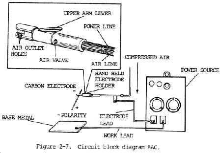
e. The circuit diagram for air carbon arc cutting or gouging is shown by /figure 2-7. Normally, conventional welding machines with constant current are used. Constant voltage can be used with this process.
f. When using a constant voltage (CV) power source precautions must be taken to operate it within its rated output of current and duty cycle.
g. Alternating current power sources having conventional drooping characteristics can also be used for special applications. AC type carbon electodes must be used.
h. Special heavy duty high current machines have been made specifically for the air carbon arc process. This is because of extremely high currents used for the large size carbon electrodes.
i. The air pressure must range from 80 to 100 psi (550 to 690 kPa). The volume of compressed air required ranges from as low as 5.0 cu ft/min. (2.5 liter/rein.) up to 50 cu ft/min. (24 liter/min.) for the largest-size carbon electrodes.
j. The air blast of air carbon arc welding will cause the molten metal to travel a very long distance. Metal deflection plates should be placed in front of the gouging operation, and all combustible materials should be moved away from the work area. At high-current levels, the mass of molten metal removed is quite large and will become a fire hazard if not properly contained.
k. A high noise level is associated with air carbon arc welding. At high currents with high air pressure a very loud noise occurs. Ear protection, ear muffs or ear plugs must be worn by the arc cutter.
Section IV. SAFETY PRECAUTIONS FOR GAS SHIELDED ARC WELDING
2-17. POTENTIAL HAZARDS
When any of the welding processes are used, the shielded from the air in order to obtain a high molten puddle of metal should be quality weld deposit. In shielded metal arc welding, shielding from the air is accomplished by gases produced by the disintegration of the coating in the arc. With gas shielded arc welding, shielding from the air is accomplished by surrounding the arc area with a localized gaseous atmosphere throughout the welding operation at the molten puddle area.
Gas shielded arc welding processes have certain dangers associated with them. These hazards, which are either peculiar to or increased by gas shielded arc welding, include arc gases, radiant energy, radioactivity from thoriated tungsten electrodes, and metal fumes.
2-18. PROTECTIVE MEASURES
a. Gases.
(1) Ozone. Ozone concentration increases with the type of electrodes used, amperage, extension of arc tine, and increased argon flow. If welding is carried out in confined spaces and poorly ventilated areas, the ozone concentration may increase to harmful levels. The exposure level to ozone is reduced through good welding practices and properly designed ventilation systems, such as those described in paragraph 2-4.
(2) Nitrogen Oxides. Natural ventilation may be sufficient to reduce the hazard of exposure to nitrogen oxides during welding operations, provided all three ventilation criteria given in paragraph 2-4 are satisfied. Nitrogen oxide concentrations will be very high when performing gas tungsten-arc cutting of stainless steel using a 90 percent nitrogen-10 percent argon mixture. Also, high concentrations have been found during experimental use of nitrogen as a shield gas. Good industrial hygiene practices dictate that mechanical ventilation, as defined in paragraph 2-4, be used during welding or cutting of metals.
(3) Carbon Dioxide and Carbon Monoxide. Carbon dioxide is disassociated by the heat of the arc to form carbon monoxide. The hazard from inhalation of these gases will be minimal if ventilation requirements found in paragraph 2-4 are satisfied.
WARNING
The vapors from some chlorinated solvents (e.g., carbon tetrachloride, trichloroethylene, and perchloroethylene) break down under the ultra-violet radiation of an electric arc and forma toxic gas. Avoid welding where such vapors are present. Furthermore, these solvents vaporize easily and prolonged inhalation of the vapor can be hazardous. These organic vapors should be removed from the work area before welding is begun. Ventilation, as prescribed in paragraph 2-4, shall be provided for control of fumes and vapors in the work area.
(4) Vapors of Chlorinated Solvents. Ultraviolet radiation from the welding or cutting arc can decompose the vapors of chlorinated hydrocarbons, such as perchloroethylene, carbon tetrachloride, and trichloroethylene, to form highly toxic substances. Eye, nose, and throat irritation can result when the welder is exposed to these substances. Sources of the vapors can be wiping rags, vapor degreasers, or open containers of the solvent. Since this decompsition can occur even at a considerable distance from the arc, the source of the chlorinated solvents should be located so that no solvent vapor will reach the welding or cutting area.
b. Radiant Energy. Electric arcs, as well as gas flames, produce ultraviolet and infrared rays which have a harmful effect on the eyes and skin upon continued or repeated exposure. The usual effect of ultraviolet is to “sunburn” the surface of the eye, which is painful and disabling but generally temporary. Ultraviolet radiation may also produce the same effects on the skin as a severe sunburn. The production of ultraviolet radiation doubles when gas-shielded arc welding is performed. Infrared radiation has the effect of heating the tissue with which it comes in contact. Therefore, if the heat is not sufficient to cause an ordinary thermal burn, the exposure is minimal. Leather and WoOl clothing is preferable to cotton clothing during gas-shielded arc welding. Cotton clothing disintegrates in one day to two weeks, presumably because of the high ultraviolet radiation from arc welding and cutting.
c. Radioactivity from Thoriated Tungsten Electrodes. Gas tungsten-arc welding using these electrodes may be employed with no significant hazard to the welder or other room occupants. Generally, special ventilation or protective equipment other than that specified in paragraph 2-4 is not needed for protection from exposure hazards associated with welding with thoriated tungsten electrodes.
d. Metal Fumes. The physiological response from exposure to metal fumes varies depending upon the metal being welded. Ventilation and personal protective equipment requirements as prescribed in paragraph 2-4 shall be employed to prevent hazardous exposure.
Section V. SAFETY PRECAUTIONS FOR WELDING AND CUTTING CONTAINERS THAT HAVE HELD COMBUSTIBLES
2-19. EXPLOSION HAZARDS
a. Severe explosions and fires can result from heating, welding, and cutting containers which are not free of combustible solids, liquids, vapors, dusts, and gases. Containers of this kind can be made safe by following one of the methods described in paragraphs 2-22 through 2-26. Cleaning the container is necessary in all cases before welding or cutting.
WARNING
Do not assume that a container that has held combustibles is clean and safe until proven so by proper tests. Do not weld in places where dust or other combustible particles are suspended in air or where explosive vapors are present. Removal of flammable material from vessels and/or containers may be done either by steaming out or boiling.
b. Flammable and explosive substances may be present in a container because it previously held one of the following substances:
(1) Gasoline, light oil, or other volatile liquid that releases potentially hazardous vapors at atomspheric pressure.
(2) An acid that reacts with metals to produce hydrogen.
(3) A nonvolatile oil or a solid that will not release hazardous vapors at ordinary temperatures, but will release such vapors when exposed to heat.
(4) A combustible solid; i. e., finely divided particles which may be present in the form of an explosive dust cloud.
c. Any container of hollow body such as a can, tank, hollow compartment in a welding, or a hollow area on a casting, should be given special attention prior to welding. Even though it may contain only air, heat from welding the metal can raise the temperature of the enclosed air or gas to a dangerously high pressure, causing the container to explode. Hollow areas can also contain oxygen-enriched air or fuel gases, which can be hazardous when heated exposed to an arc or or flame. Cleaning the container is necessary in all cases before cutting or welding.
2-20. USING THE EXPLOSIMETER
a. The explosimeter is an instrument which can quickly measure an atomsphere for concentrations of flammable gases and vapors.
b. It is important to keep in mind that the explosimeter measures only flammable gases and vapors. For example, an atomsphere that is indicated non-hazardous from the standpoint of fire and explosion may be toxic if inhaled by workmen for some time.
c. Model 2A Explosimeter is a general purpose combustible gas indicator. It will not test for mixtures of hydrogen, acetylene, or other combustibles in which the oxygen content exceeds that of normal air (oxygen-enriched atomspheres). Model 3 Explosimeter is similar except that it is equipped with heavy duty flashback arresters which are capable of confining within the combustion chambers explosions of mixtures of hydrogen or acetylene and oxygen in excess of its normal content in air. Model 4 is designed for testing oxygen-acetylene mixtures and is calibrated for acetylene.
d. Testing Atomspheres Contaminated with Leaded Gasoline. When an atomsphere contaminated with lead gasoline is tested with a Model 2A Explosimeter, the lead produces a solid product of combustion which, upon repeated exposure, may develop a coating upon the detector filament resulting in a loss of sensitivity. To reduce this possibility, an inhibitor-filter should be inserted in place of the normal cotton filter in the instrument. This device chemically reacts with the tetraethyl lead vapors to produce a more volatile lead compound. One inhibitor-filter will provide protection for an instrument of eight hours of continuous testing.
CAUTION
Silanes, silicones, silicates, and other compounds containing silicon in the test atomsphere may seriously impair the response of the instrument. Some of these materials rapidly “poison” the detector filament so that it will not function properly. When such materials are even suspected to be in the atmosphere being tested, the instrument must be checked frequently (at least after 5 tests). Part no. 454380 calibration test kit is available to conduct this test. If the instrument reads low on the test gas, immediately replace the filament and the inlet filter.
e. Operation Instructions. The MSA Explosimeter is set in its proper operating condition by the adjustment of a single control. This control is a rheostat regulating the current to the Explosimeter measuring circuit. The rheostat knob is held in the “OFF” position by a locking bar. This bar must be lifted before the knob can be turned from “OFF” position.
To test for combustible gases or vapors in an atomsphere, operate the Model 2A Explosimeter as follows:
(1) Lift the left end of the rheostat knob “ON-OFF” bar and turn the rheostat knob one quarter turn clockwise. This operation closes the battery circuit. Because of unequal heating or circuit elements, there will be an initial deflection of the meter pointer. The meter pointer may move rapidly upscale and then return to point below “ZERO”, or drop directly helm “ZERO”.
(2) Flush fresh air through the instrument. The circuit of the instrument must be balanced with air free of combustible gases or vapors surrounding the detector filament. Five squeezes of the aspirator bulb are sufficient to flush the combustion chamber. If a sampling line is used, an additional two squeezes will be required for each 10 ft (3m) of line.
(3) Adjust rheostat knob until meter pointer rests at “ZERO”. Clockwise rotation of the rheostat knob causes the meter pointer to move up scale. A clockwise rotation sufficient to move the meter pointer considerably above “ZERO” should be avoided as this subjects the detector filament to an excessive current and may shorten its life.
(4) Place end of sampling line at, or transport the Model 2A Explosimeter to, the point where the sample is to be taken.
(5) Readjust meter pointer to “ZERO” if necessary by turning rheostat knob.
(6) Aspirate sample through instrument until highest reading is obtained. Approximately five squeezes of the bulb are sufficient to give maximum deflection. If a sampling line is used, add two squeezes for each 10 ft (3 m) of line. This reading indicates the concentration of combustible gases or vapors in the sample.
The graduations on the scale of the indicating inter are in percent of the lower explosive limit. Thus, a deflection of the meter pointer between zero and 100 percent shins how closely the atmosphere being tested approaches the minimum concentration required for the explosion. When a test is made with the instrument and the inter pointer is deflected to the extreme right side of the scale and remains there, the atmosphere under test is explosive.
If the meter pointer moves rapidly across the scale, and on continued aspiration quickly returns to a position within the scale range or below “ZERO”, it is an indication that the concentration of flammable gases or vapors may be above the upper explosive limit. To verify this, immediately aspirate fresh air through the sampling line or directly into the instrument. Then, if the meter pointer moves first to the right and then to the left of the scale, it is an indication that the concentration of flammable gas or vapor in the sample is above the upper explosive limit.
When it is necessary to estimate or compare concentrations of combustible gases above the lower explosive limit a dilution tube may be employed. See paragraph 2-20 f (1).
The meter scale is red above 60 to indicate that gas concentrations within that range are very nearly explosive. Such gas-air mixtures are considered unsafe.
(7) To turn instrument off: Rotate rheostat knob counterclockwise until arrow on knob points to “OFF”. The locking bar will drop into position in its slot indicating that the rheostat is in the “OFF” position.
NOTE
When possible, the bridge circuit balance should be checked before each test. If this is not practical, the balance adjustment should be made at 3-minute internals during the first ten minutes of testing and every 10 minutes thereafter.
f. Special Sampling Applications
(1) Dilution tube. For those tests in which concentrations of combustible gases in excess of liner explosive limit concentrations (100 percent on instrument inter) are to be compared, such as in testing bar holes in the ground adjacent to a leak in a buried gas pipe, or in following the purging of a closed vessel that has contained f flammable gases or vapors, a special air-dilution tube must be used. Such dilution tubes are available in 10:1 and 20:1 ratios of air to sample, enabling rich concentrations of gas to be compared.
In all tests made with the dilution tube attached to the instrument, it is necessary that the instrument be operated in fresh air and the gaseous sample delivered to the instrument through the sampling line in order to permit a comparison of a series of samples beyond the normal range of the instrument to determine which sample contains the highest concentration of combustible gases. The tube also makes it possible to folbw the progress of purging operation when an atomsphere of combustibles is being replaced with inert gases.
(2) Pressure testing bar holes. In sane instances when bar holes are drilled to locate pipe line leaks, a group of holes all containing pure gas may be found. This condition usually occurs near a large leak. It is expected that the gas pressure will be greatest in the bar hole nearest the leak. The instrument may be used to locate the position of the leak by utilizing this bar hole pressure. Observe the time required for this pressure to force gas through the instrument sampling line. A probe tube equipped with a plug for sealing off the bar hole into which it is inserted is required. To remove the flow regulating orifice from the instrument, aspirate fresh air through the Explosimeter and unscrew the aspirator bulb coupling. Adjust the rheostat until the meter pointer rests on “ZERO”.
The probe tube is now inserted in the bar hole and sealed off with the plug. Observe the time at which this is done. Pressure developed in the bar hole will force gas through the sampling line to the instrument, indicated by an upward deflection of the meter pointer as the gas reaches the detector chamber.
Determine the time required for the gas to pass through the probe line. The bar hole showing the shortest time will have the greatest pressure.
When the upward deflection of the meter pointer starts, turn off the instrument, replace the aspirator bulb and flush out the probe line for the next test.
2-21. PREPARING THE CONTAINER FOR CLEANING
CAUTION
Do not use chlorinated hydrocarbons, such as trichloroethylene or carbon tetrachloride, when cleaning. These materials may be decomposed by heat or radiation from welding or cutting to form phosgene. Aluminum and aluminum alloys should not be cleaned with caustic soda or cleaners having a pH above 10, as they may react chemically. Other nonferrous metals and alloys should be tested for reactivity prior to cleaning.
NOTE
No container should be considered clean or safe until proven so by tests. Cleaning the container is necessary in all cases before welding or cutting.
a. Disconnect or remove from the vicinity of the container all sources of ignition before starting cleaning.
b. Personnel cleaning the container must be protected against harmful exposure. Cleaning should be done by personnel familiar with the characteristics of the contents.
c. If practical, move the container into the open. When indoors, make sure the room is well ventilated so that flammable vapors may be carried away.
d. Empty and drain the container thoroughly, including all internal piping, traps, and standpipes. Removal of scale and sediment may be facilitated by scraping, hammering with a nonferrous mallet, or using a nonferrous chain as a srubber. Do not use any tools which may spark and cause flammable vapors to ignite. Dispose of the residue before starting to weld or cut.
e. Identify the material for which the container was used and determine its flammability and toxicity characteristics. If the substance previously held by the container is not known, assure that the substance is flammable, toxic, and insoluble in water.
f. Cleaning a container that has held combustibles is necessary in all cases before any welding or cutting is done. This cleaning may be supplemental by filling the container with water or an inert gas both before and during such work.
g. Treat each compartment in a container in the same manner, regardless of which comparment is be welded or cut.
2-22. METHODS OF PRECLEANING CONTAINERS WHICH HAVE HELD FLAMMABLE LIQUIDS
a. General. It is very important for the safety of personnel to completely clean all tanks and containers which have held volatile or flammable liquids. Safety precautions cannot be over-emphasized because of the dangers involved when these items are not thoroughly purged prior to the application of heat, especially open flame.
b. Accepted Methods of Cleaning. Various methods of cleaning containers which have held flammable liquids are listed in this section. However, the automotive exhaust and steam cleaning methods are considered by military personnel to be the safest and easiest methods of purging these containers.
2-23. AUTOMOTIVE EXHAUST METHOD OF CLEANING
WARNING
Head and eye protection, rubber gloves, boots, and aprons must be worn when handling steam, hot water, and caustic solutions. When handling dry caustic soda or soda ash, wear approved respiratory protective equipment, long sleeves, and gloves. Fire resistant hand pads or gloves must be worn when handling hot drums.The automotive exhaust method of cleaning should be conducted only in well-ventilated areas to ensure levels of toxic exhaust gases are kept below hazardous levels.
CAUTION
Aluminum and aluminum alloys should not be cleaned with caustic soda or cleaners having a pH above 10, as they may react chemically. Other nonferrous metals and alloys should be investigated for reactivity prior to cleaning.
a. Completely drain the container of all fluid.
b. Fill the container at least 25 percent full with a solution of hot soda or detergent (1 lb per gal of water (0.12 kg per 1)) and rinse it sufficiently to ensure that the inside surface is thoroughly finished.
c. Drain the solution and rinse the container again with clean water.
d. Open all inlets and outlets of the container.
e. Using a flexible tube or hose, direct a stream of exhaust gases into the container. Make sure there are sufficient openings to allow the gases to flow through the container.
f. Allow the gases to circulate through the container for 30 minutes.
g. Disconnect the tube from the container and use compressed air (minimum of 50 psi (345 kPa)) to blow out all gases.
h. Close the container openings. After 15 minutes, reopen the container and test with a combustible gas indicator. If the vapor concentration is in excess of 14 percent of the lower limit of flammability, repeat cleaning procedure.
2-24. STEAM METHOD OF CLEANING
WARNING
Head and eye protection, rubber gloves, boots, and aprons must be worn when handling steam, hot water, and caustic solutions. When handling dry caustic soda or soda ash, wear approved respiratory protective equipment, long sleeves, and gloves. Fire resistant hand pads or gloves must be worn when handling hot drums.The automotive exhaust method of cleaning should be conducted only in well-ventilated areas to ensure levels of toxic exhaust gases are kept below hazardous levels.
CAUTION
Aluminum and aluminum alloys should not be cleaned with caustic soda or cleaners having a pH above 10, as they may react chemically. Other nonferrous metals, and alloys should be investigated for reactivity prior to cleaning.
a. Completely drain the container of all fluid.
b. Fill the container at least 25 percent full with a solution of hot soda, detergent, or soda ash (1 lb per gal of water (0.12 kg per 1)) and agitate it sufficiently to ensure that the inside surfaces are thoroughly flushed.
NOTE
Do not use soda ash solution on aluminum.
c. Drain the solution thoroughly.
d. Close all openings in the container except the drain and filling connection or vent. Use damp wood flour or similar material for sealing cracks or other damaged sections.
e. Use steam under low pressure and a hose of at least 3/4-in. (19.05 mm) diameter. Control the steam pressure by a valve ahead of the hose. If a metal nozzle is used at the outlet end, it should be made of nonsparkinq material and should be electrically connected to the container. The container, in turn, should be grounded to prevent an accumulation of static electricity.
f. The procedure for the steam method of cleaning is as follows:
(1) Blow steam into the container, preferably through the drain, for a period of time to be governed by the condition or nature of the flammable substance previously held by the container. When a container has only one opening, position it so the condensate will drain from the same opening the steam inserted into. (When steam or hot water is used to clean a container, wear suitable clothing, such as boots, hood, etc., to protect against burns.)
(2) Continue steaming until the container is free from odor and the metal parts are hot enough to permit steam vapors to flow freely out of the container vent or similar opening. Do not set a definite time limit for steaming containers since rain, extreme cold, or other weather conditions may condense the steam as fast as it is introduced. It may take several hours to heat the container to such a temperature that steam will flow freely from the outlet of the container.
(3) Thoroughly flush the inside of the container with hot, preferably boiling, water.
(4) Drain the container.
(5) Inspect the inside of the container to see if it is clean. To do this, use a mirror to reflect light into the container. If inspection shows that it is not clean, repeat steps (1) through (4) above and inspect again. (Use a nonmetal electric lantern or flashlight which is suitable for inspection of locations where flammable vapors are present.)
(6) Close the container openings. In 15 minutes, reopen the container and test with a combustible gas indicator. If the vapor concentration is in excess of 14 percent of the lower limit of flammbility, repeat the cleaning procedure.
2-25. WATER METHOD OF CLEANING
a. Water-soluble substances can be removed by repeatedlv filling and draining the container with water. Water-soluble acids, acetone, and alcohol can be removed in this manner. Diluted acid frequently reacts with metal to produce hydrogen; care must be taken to ensure that all traces of the acid are removed.
b. When the original container substance is not readily water-soluble, it must be treated by the steam method or hot chemical solution method.
2-26. HOT CHEMICAL SOLUTION METHOD OF OF CLEANING
WARNING
Wear head and eye protection, rubber gloves, boots, and aprons when handling steam, hot water, and caustic solutions. When handling dry caustic soda or soda ash, wear approved respiratory protective equipment, long sleeves, and gloves. Wear fire resistant hand pads or gloves to handle hot drums.
CAUTION
Aluminum and aluminum alloys should not be cleaned with caustic soda or cleaners having a pH above 10, as they may react chemically. Other nonferrous metals and alloys should be investigated for reactivity prior to cleaning.
a. The chemicals generally used in this method are trisodium phosphate (strong washing powder) or a commercial caustic cleaning compound dissolved in water to a concentration of 2 to 4 oz (57 to 113 g) of chemical per gallon of water.
b. The procedure for the hot chemical solution method of cleaning is as follows:
(1) Close all container openings except the drain and filling connection or vent. Use damp wood flour or similar material for sealing cracks or other damaged sections.
(2) Fill the container to overflowing with water, preferably letting the water in through the drains. If there is no drain, flush the container by inserting the hose through the filling connection or vent. Lead the hose to the bottom of the container to get agitation from the bottom upward. This causes any remaining liquid, scum, or sludge to be carried upward and out of the container.
(3) Drain the container thoroughly.
(4) Completely dissolve the amount of chemical required in a small amount of hot or boiling water and pour this solution into the container. Then fill the container with water.
(5) Make a steam connection to the container either through the drain connection or by a pipe entering through the filling connection or vent. Lead the steam to the bottom of the container. Admit steam into the chemical solution and maintain the solution at a temperature of 170 to 180°F (77 to 82°C). At intervals during the steaming, add enough water to permit overflying of any volatile liquid, scum, or sludge that may have collected at the top. Continue steaming to the point where no appreciable amount of volatile liquid, scum, or sludge appears at the top of the container.
(6) Drain the container.
(7) Inspect the inside of the container as described in paragraph 2-24 f (5). If it is not clean, repeat steps (4) thru (6) above and inspect again.
(8) Close the container openings. In 15 minutes, test the gas concentration in the container as described in paragraph 2-24 f (6).
c. If steaming facilities for heating the chemical solution are not available, a less effective method is the use of a cold water solution with the amount of cleaning compound increased to about 6 oz (170 g) per gal of water. It will help if the solution is agitated by rolling the container or by blowing air through the solution by means of an air line inserted near the bottom of the container.
d. Another method used to clean the container is to fill it 25 percent full with cleaning solution and clean thoroughly, then introduce low pressure steam into the container, allowing it to vent through openings. Continue to flow steam through the container for several hours.
2-27. MARKING OF SAFE CONTAINERS
After cleaning and testing to ensure that a container is safe for welding and cutting, stencil or tag it. The stencil or tag must include a phrase, such as “safe for welding and cutting,” the signature of the person so certifying, and the date.
2-28. FILLING TREATMENT
It is desirable to fill the container with water during welding or cutting as a supplement to any of the cleaning methods (see /fig. 2-8). Where this added precaution is taken, place the container so that it can be kept find to within a few inches of the point where the work is to be done. Make sure the space above the water level is vented so the heated air can escape from the container.

2-29. PREPARING THE CLEAN CONTAINER FOR WELDING OR CUTTING–INERT GAS TREATMENT
a. General. Inert gas may be used as a supplement to any of the cleaning methods and as an alternative to the water filling treatment. If sufficient inert gas is mixed with flammable gases and vapors, the mixture will come non-flammable. A continuous flow of steam may also be used. The steam will reduce the air concentration and make the air flammable gas mixture too lean to burn. Permissible inert gases include carbon dioxide and nitrogen.
b. Carbon Dioxide and Nitrogen.
(1) When carbon dioxide is used, a minimum concentration of 50 percent is required, except when the falmmable vapor is principally hydrogen, carbon monoxide, or acetylene. In these cases, a minimum concentration of 80 percent carbon dioxide is required. Carbon dioxide is heavier than air, and during welding or cutting operations will tend to remain in containers having a top opening.
(2) When nitrogen is used, the concentrations should be at least 10 percent greater than those specified for carbon dioxide.
(3) Do not use carbon monoxide.
c. Procedure. The procedure for inert gas, carbon dioxide, or nitrogen treatment is as follows:
(1) Close all openings in the container except the filling connection and vent. Use damp wood flour or similar material for sealing cracks or other damaged sections.
(2) Position the container so that the spot to be welded or cut is on top. Then fill it with as much water as possible.
(3) Calculate the volume of the space above the water level and add enough inert gas to meet the minimum concentration for nonflammability. This will usually require a greater volume of gas than the calculated minimum, since the inert gas may tend to flow out of the vent after displacing only part of the previously contained gases or vapors.
(4) Introduce the inert gas, carbon dioxide, or nitrogen from the cylinder through the container drain at about 5 psi (34.5 kPa). If the drain connection cannot be used, introduce the inert gas through the filling opening or vent. Extend the hose to the bottom of the container or to the water level so that the flammable gases are forced out of the container.
(5) If using solid carbon dioxide, crush and distribute it evenly over the greatest possible area to obtain a rapid formation of gas.
d. Precautions When Using Carbon Dioxide. Avoid bodily contact with solid carbon dioxide, which may produce “burns”. Avoid breathing large amounts of carbon dioxide since it may act as a respiratory stimulant, and, in sufficient quantities, can act as an asphyxiant.
e. Inert Gas Concentration. Determine whether enough inert gas is present using a combustible gas indicator instrument. The inert gas concentration must be maintained during the entire welding or cutting operation. Take steps to maintain a high inert gas concentration during the entire welding or cutting operation by one of the following methods:
(1) If gas is supplied from cylinders, continue to pass the gas into the container.
(2) If carbon dioxide is used in solid form, add small amounts of crushed solid carbon dioxide at intervals to generate more carbon dioxide gas.
Section VI. SAFETY PRECAUTIONS FOR WELDING AND CUTTING POLYURETHANE FOAM FILLED ASSEMBLIES
2-30. HAZARDS OF WELDING POLYURETHANE FOAM FILLED ASSEMBLIES
WARNING
Welding polyurethane foam-filled parts can produce toxic gases. Welding should not be attempted on parts filled with polyurethane foam. If repair by welding is necessary, the foam must be removed from the heat-affected area, including the residue, prior to welding.
a. General. Welding polyurethane foam filled parts is a hazardous procedure. The hazard to the worker is due to the toxic gases generated by the thermal breakdown of the polyurethane foam. The gases that evolve from the burning foam depend on the amount of oxygen available. Combustion products of polyurethane foam in a clean, hot fire with adequate oxygen available are carbon dioxide, water vapor, and varying amounts of nitrogen oxides, carbon monoxide, and traces of hydrogen cyanide. Thermal decomposition of polyurethanes associated with restricted amounts of oxygen as in the case of many welding operations results in different gases being produced. There are increased amounts of carbon monoxide, various aldehydes, isocyanates and cyanides, and small amounts of phosgene, all of which have varying degrees of toxicity.
b. Safety Precautions.
(1) It is strongly recommended that welding on polyurethane foam filled parts not be performed. If repair is necessary, the foam must be removed from the heataffected zone. In addition, all residue must be cleaned from the metal prior to welding.
(2) Several assemblies of the M113 and M113A1 family of vehicles should not be welded prior to removal of polyurethane foam and thorough cleaning.


